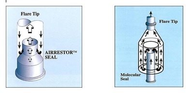
Velocity purge seal mounted in base of flare tip and uses the velocity of the purge gas through the seal to sweep any atmospheric air in the flare tip. Flare Tip Molecular Seal.

Molecular Seals Afg Combustion
Parameters for Properly Designed and Operated Flares Report for Flare Review Panel April 2012 Prepared by US.

. Figure 1 - Schematic of a buoyancy seal in a flare stack indicating purge gas path. What is Molecular seal in flare system. PG purge gas m3h ft3h B constant for flare stacks 457914 mm 1836 in in diameter 12 x 10-5 metric.
AFS MOLECULAR SEALS The Molecular Seal AFS Series is located just below the flare tip and has been designed to prevent air ingress to the flare riser thus preventing the formation of an explosive mixture in the system. Liquid seals at base of flare stack. The large quantity of gas vented after the compressor tripped blew the oil in the molecular seal out of the flare and it ignited and formed fireballs.
EPA Office of Air Quality Planning and Standards OAQPS. They normally are located below the flare tip and serve to prevent air entry into the stack. Schematic diagram of Molecular seal Drum the baffle to seal diameter ratio should not be more than 075 when hydrocarbons are burned in the flare 289.
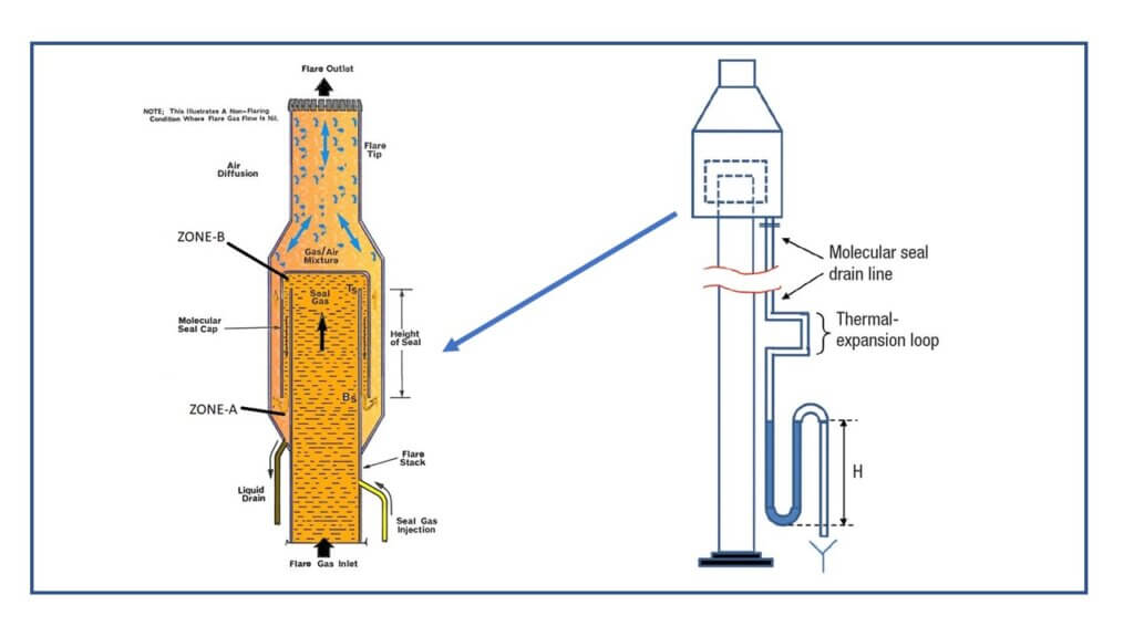
The seal is a gas inversion device causing the gas normally flowing in an upward direction to be turned through 180 degrees in the original direction of the flow. Molecular seal is an unfortunate name given to a flow restriction installed in a flare stack to minimize the amount of purge gas required. Purge flow is required to prevent air ingress into the flare stack.
The location of NAOs seal design reduces purge gas reduction but and extends. The purpose is to minimize flare gas purge rates which would otherwise be large and create velocity conditions at the tip that will minimize tip flame impingement and damage of the flare tips. Optionally there may also be an alternative gas recovery system in place.
The overflow line from the water seal at the flare stack base included an emer- gency shutoff valve that would automatically close if the level of water in the base was too low. On the other hand a water seal drum uses the same way except that the sealing fluid is water and the drum is instaled at the flare stack base after the knock-out drum vessel whereas moleculare seal is instaled at the top of flare stack before the tip. Also known as flare stacks flare tips molecular seals are elevated vertical conveyances found in oil gas wells rigs refineries chemical natural gas plants and landfills.
DuhonGATE Chemical 27 Jun 08 1751. Effective purge gas includes. The team should understand the design basis of all flare system parts and.
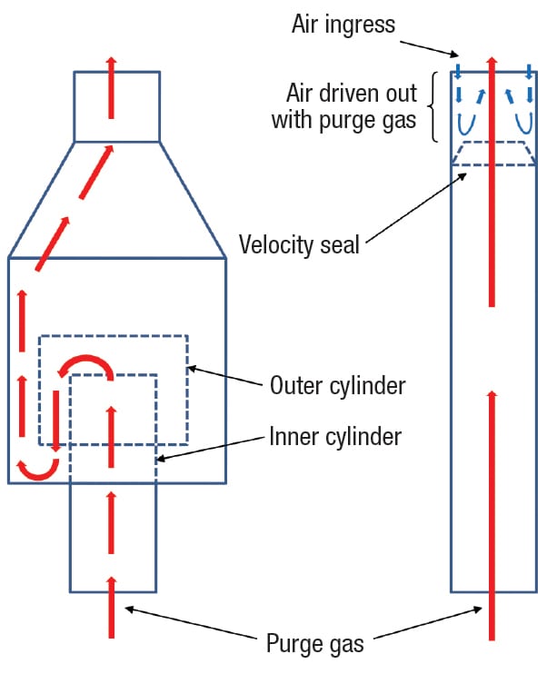
This volume allows the flow of flared gas from inlet pipe to. The seal is a gas inversion device causing the gas normally flowing in an upward direction to be turned. Buoyancy seal typically uses the difference in densities of the purge gas and ambient air to keep the air from entering flare system.
This first of two articles on flare design and components looks at elevated flares flare tips incinerator type flares flare pilots and gas seals. NAO was the first to introduce the Multi Baffle Velocity Type Purge Gas reduction seal in 1972. Buoyancy seals use a couple of concentric baffled cylinders in the path of the purge gas as indicated in figure-1.
NAOs Fluidic Flare with Multi Baffle Fluidic Seal and Solid Conical WindFlame Shield provides for minimal purge gas flow while maintaining maximum safety reliability and protection for the equipment. The Argo AMS is a standard labyrinth type used throughout the flare industry and can be used with purge gases lighter or heavier than air. The difference in purge gas and air densities sees the purge gas form a molecular barrier in either the top or in the bottom.
The Molecular Seal is located just below the flare tip and has been designed to prevent air ingress to the flare riser thus preventing the formation of an explosive mixture in the system. Air must be prevented from entering the molecular seal too far in order to coming into contact with waste gases and forming combustible mixtures. Flare System Design for Oil and Gas Installations Flare Seal Drum Primary Duty To prevent flashback from flare tip back to flare headers To avoid air ingress into flare system during sudden temperature changes and to maintain positive system pressure Design Specifications Water as liquid sealing fluid not recommended for extremely.
The flare vendor will have to provide details on design options and required. Molecular seals cause flow reversal. Molecular seals depend on the density difference between air and hydrocarbon gas.
As indicated in figure-1 liquid seal at the flare stack base is essentially a cylindrical volume of liquid into which the gas inlet to flare stack is dipped. PG BD 3 M 0565. A molecular seal also could be very efficient in reducing the amount of purge gas required to maintain a positive.
Molecular seal creates a labyrinth to more efficiently sweep any atmospheric air in the flare tip. The seal is normally flanged between the flare tip and stack and is designed to prevent air from entering the flare system. The primary object of this invention is to provide a molecular seal which would limit the entry of atmospheric air into the top end of a flare stack and into a selected portion of the molecular seal.
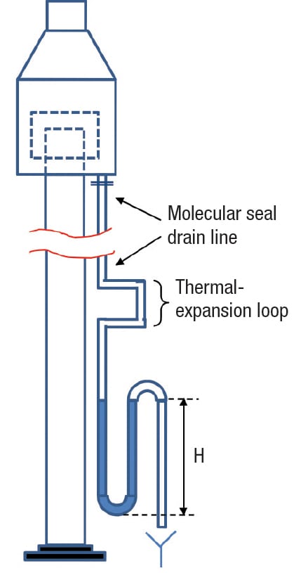
Every change introduces potential process safety hazards and needs to be evaluated by the PHA team. Figure 1 shows an image of an onshore elevated flare stack where the knock-out drum seal drum flare stack molecular seal and flare tip are all visible. The molecular seal included a drain line with a U-seal and isolation valve at the bottom.
They are used to eliminate waste gas that cannot be otherwise used or transported. Further information on typical flare system design can be found in ISO 23251 2006. DESIGN FEATURES Molecular seal can maintain an effective seal for up to 8 hours after loss of purge gas supply Velocity seal provided with weep holes to allow drainage Molecular seal complete with drain connection inspection port Both seals provide significant savings in operating costs Extends flare tip life by minimizing burn back No moving parts.
Velocity seal reduces purge gas requirement by 94. Light gas is trapped at the top of the U-tube. Molecular seal reduces purge gas requirement by 98.
You can use the following equation as an initial estimate of the purge gas rate required for an open pipe flare. These are generally used in flare systems for gas plants and others where freezing is an issue for seal pots and mol sieves. 70 customary D stack diameter mm in M molecular weight of purge gas.
Optimizing Flare Operation Through Proper Design Chemical Engineering Page 1

Pdf Purge Reduction Device A Guide To The Selection Of Gas Seal In A Flare System
Basics Of Flare System In Any Operating Plant Design And Engineering
Optimizing Flare Operation Through Proper Design Chemical Engineering Page 1

Buoyancy Seal And Velocity Seal For Flare Stack Enggcyclopedia
Flare System Part Flare Process Flare Drums Flare Seals The Piping Talk
Buoyancy Seal And Velocity Seal For Flare Stack Enggcyclopedia
Schematic Diagram Of Molecular Seal Drum The Baffle To Seal Diameter Download Scientific Diagram
0 comments
Post a Comment